
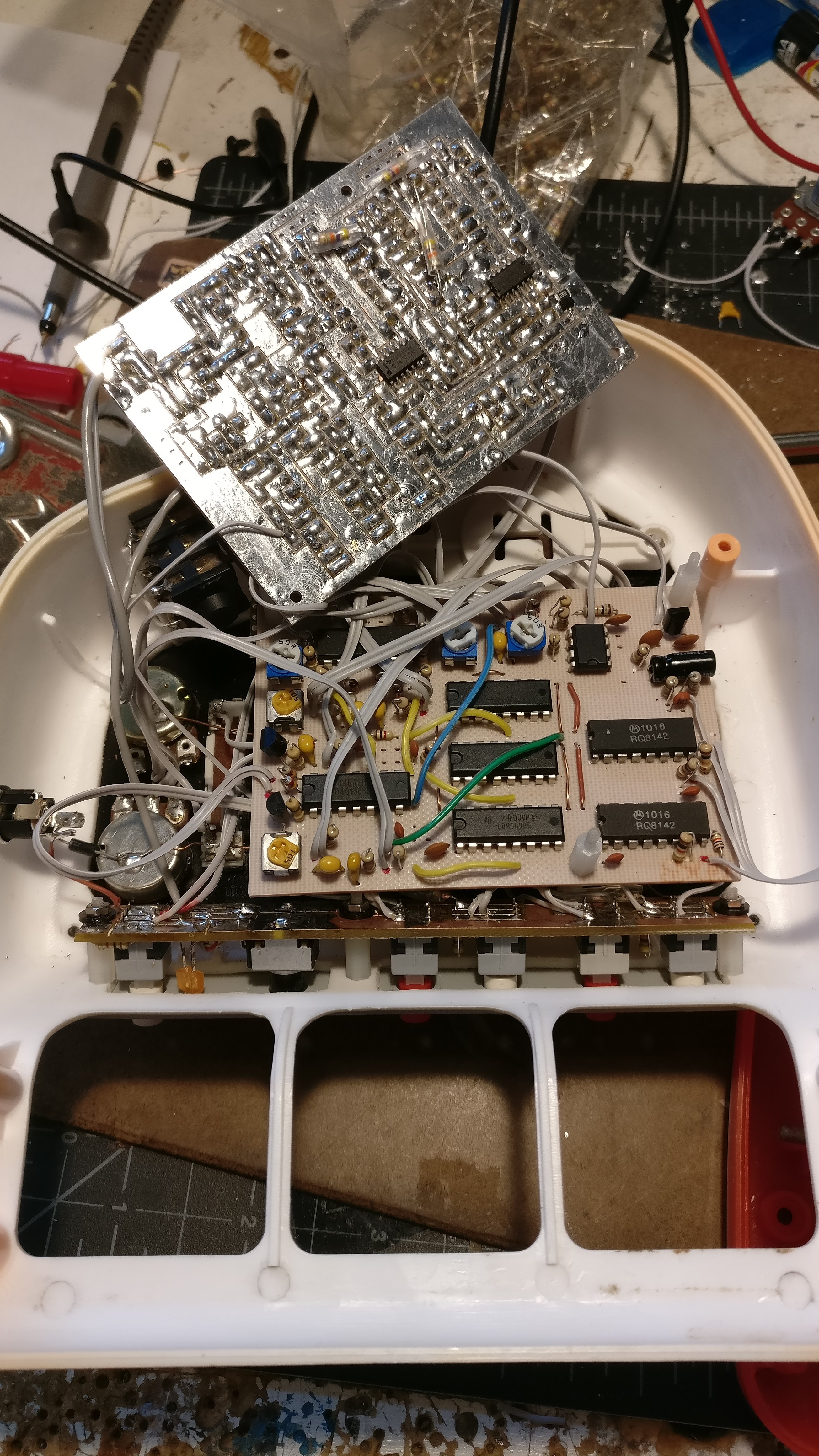
While cleaning shop, I came across an old friend. I built this little keyboard monster back in 2013. The FUNKY GLITCH BUDDY was an interesting concept, but it suffered from some pretty challenging design flaws that I had always wanted to fix, but never had the time. For one, the keyboard would draw so much current due to the fact that the keys were all infrared proximity sensors. There were a lot of 7400 series chips and opto-isolators in the design too, so overall this thing was pretty inefficient and noisy. Two of the voices were 8-bit LFSR noise generators which didn't particularly sound like noise. The third oscillator was a basic two transistor oscillator that I ripped out of a cheap organ toy, and had died some time ago. At the time of this build, I had just started using my CNC to engrave and cut my own circuit boards. This was my first project using the CNC, and the design and orientation was pretty sloppy. Everything was jammed together, and I never even took the time to draw out my schematics, so finding and fixing problems years later was difficult to do. Instead I thought it would be quicker and more fun to just completely redesign the circuit.
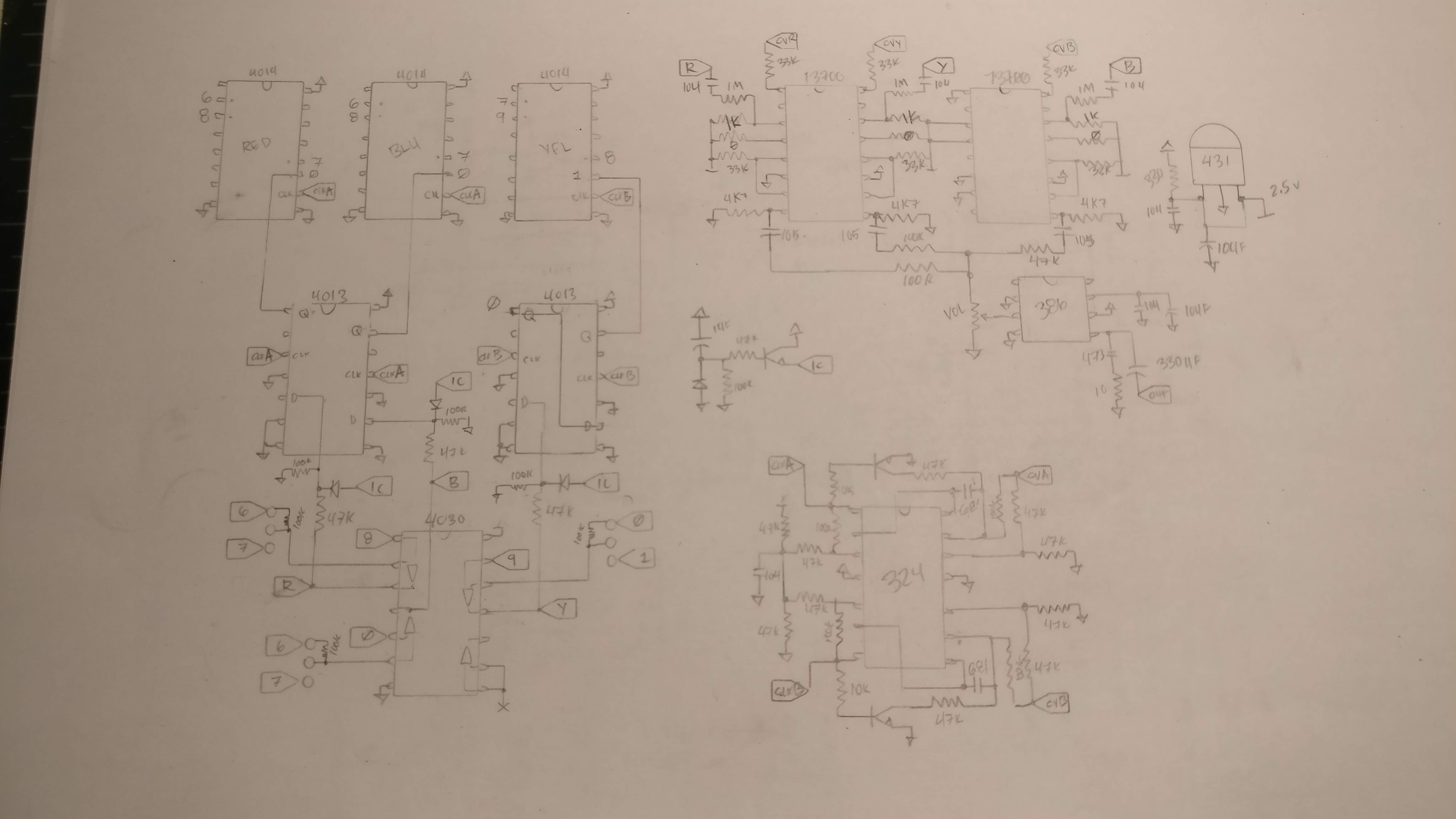
The concept for the new version would pretty much stay the same, but there would be three LFSR noise generators instead of just two, and the pattern select keys would just cycle through the patterns rather than shifting through patterns depending on how far down the key was pressed. I replaced all of the 7400 series chips with their 4000 series counterparts, and got rid of any opto-isolators and unnecessary reference voltage trimmers. I used OTA VCA's. Unfortunately I hadn't yet discovered the Lunetta style diode VCA' at this point, which would have been perfect for this application... Oh well. Since the pattern select switches were sequential, I had three extra switches to make use of. The original design could only shift through 8 patterns with the variable-press keys, so I had "SHIFT" switches for each pattern to access the other 8 available patterns. Now that I didn't need the shift switches, I used them to set different taps for the LFSR noise generators. I have found that when it comes to LFSR noise, there are certain bit lengths that sound better than others, and they are not always the longest. Shifting the taps is a nice feature but can be problematic sometimes, because shifting the inputs can sometimes cause the LFSR to lose its "SEED"... Without going too far into LFSR's, I'll just say it was a little troublesome towards the end but I was able to create stable LFSR's with a little trial and error. I found that the more finicky tap combinations preferred CD4014 to CD4021 chips, which I don't fully understand why, but whatever, they work..
I had to get creative with some limitations to the interface, too, since there was no "freq" or "lfo" hardware for the voice that had been the toy organ oscillator. The pitch and LFO of the third(red) voice is shared with the second(blue), and the "amt" control is an attenu-verter, so the third voice can not be totally attenuated with the VCA. However, one of the 16 patterns is 0000000000000000, so it is possible to mute the voice that way.
The new circuitry was pretty easy to design and prototype on breadboard. I tend to use my CNC less and less these days since ordering PCB's from china is so affordable and easy. It seemed fitting that I design and cut all of my circuit boards with my CNC for this project since it was the first ever project I used the CNC for. Designing circuit boards this way is pretty challenging and frustrating sometimes, but it is gratifying when it comes out.
The FUNKY GLITCH BUDDY is now finally up to my liking and it is pretty fun to play.


 |


This was really cool. Thanks for sharing that video of the final product.
ReplyDelete